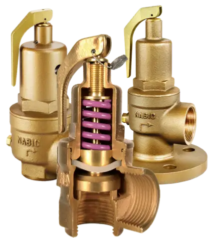
NABIC Valves
Valve Safety Information
Installation, Testing, Re-calibration & Maintenance
PLANT SAFETY
In recent years, plant safety, in particular, boiler safety, has become a bigger issue for insurance companies in commercial and industrial buildings. Along with carrying out an annual plant inspection, insurance companies now usually insist on yearly re-calibration, with certificate, of safety valves to ensure correct function if and when called upon to protect the system from increasing pressures.
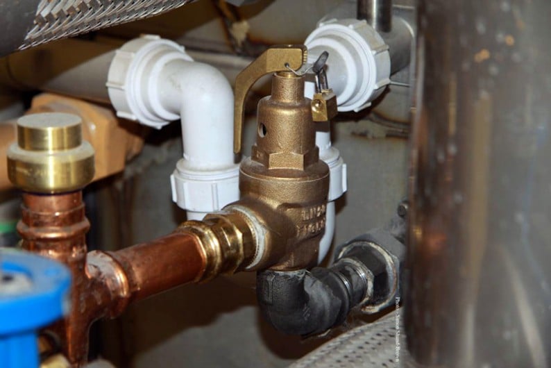
INSTALLATION
General
Before installation, all inlet pipework should be thoroughly cleaned and flushed through to remove any particles of foreign matter. Care should be taken to avoid excessive use of PTFE tape or sealing compound. Inlet and outlet pipework should be of sufficient strength to withstand the reaction forces created when the safety valve discharges. It should be installed in such a way that no undue stress or vibration is transmitted to the valve.
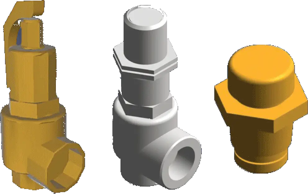
Valve
Protective caps should not be removed from the safety valve until immediately prior to installation. The valve should be mounted vertically with the test lever uppermost.
Inlet
The safety valve inlet connection, as indicated by the body arrow marking, should be attached to the vessel or pipeline using the shortest possible length of pipe, with no intervening isolation valve (i.e. the pressure loss at the inlet to the safety valve at flowing conditions should not exceed 3% of the set pressure of the safety valve (BS EN ISO 4126-1). Inlet pipework must have across-sectional area at least equal to that of the safety valve inlet. Where the inlet pipework is flanged, it must be flat and fitted with a full face joint. For temperature relief valves, special care should be taken to check that no fouling of the thermal element, or restriction of flow, occurs when the valve is installed. It is also important to ensure that, where installed directly into a water heater, the temperature sensing element is immersed within the top 150mm of the heater (this is where the hottest water is located in the vessel).
Outlet
Discharge pipework should be as short as possible, with across-sectional area at least equal to that of the safety valve outlet and should be designed to limit the built-up back pressure to 10% of the safety valve set pressure, when the valve is discharging the certified discharge capacity (BS EN ISO 4126-1). It should be adequately supported and directed to a safe, visible point of discharge. There must be no flow restrictionor isolating valve fitted to discharge pipework. For liquid relief applications, discharge pipework should be installed with a continuous downward gradient to assist drainage and prevent any build-up back pressure within the safety valve. Where discharge pipework is directed upwards, an open drain must be provided at its lowest point. Some large size valves have a body tapping for the purpose.
When multiple valves have a common discharge pipe, it should be large enough so that when one or more valves are discharging, the superimposed back pressure on the remaining valves does not have a significant effect on their operational and flow characteristic.
FUNCTIONAL TESTING
It is the responsibility of the user to carry out a ‘risk assessment’ to establish the frequency of manual testing and re-calibration requirements.
Manual
As a minimum requirement, NABIC recommends that the mechanical operation of safety valves should be checked at three monthly intervals by manually operating the test lever. While operating the test lever, to avoid unnecessary strain on the easing gear, the valve should be under a pressure of not less than 75% of its set pressure. Safety precautions should be taken to protect personnel whilst testing is being carried out. Where arduous conditions of service exist, more frequent testing will be required.
RE-CALIBRATION
Pressure
The set pressure of NABIC safety valves should be checked every twelve months, unless the risk assessment has specified a different frequency, and a calibration certificate issued where required. This can be carried out with the valve in situ or by removal to an authorised pressure test facility. In practice, in-situ re-calibration proves difficult because the system pressure gauges need to be individually calibrated and certified. Removal to an authorised test facility ensures testing on certified equipment. Before removing the valve, steps should be taken to ensure that the system has been de-pressured.
Temperature
The opening temperature of combined pressure & temperature relief valves should be checked every twelve months, unless the risk assessment has specified a different frequency. This can be carried out in situ or by removal to a temperature test facility. The same safety precautions apply for pressure testing.
Accumulation
In addition to the above tests, full functional pressure accumulation tests under emergency conditions, may be requested by the inspection authority certifying the safety of the plant. These tests should only be carried out under the supervision of qualified personnel.
General
If a safety valve malfunctions during any of the above tests, it should be returned to an authorised test facility for repair. The system should be maintained by the immediate fitting of a calibrated replacement valve, or by rendering the plant inoperable.
MAINTENANCE
The internal condition of a safety valve should be periodically examined to ensure that there is no build-up of deposits likely to cause malfunctioning of the valve or restriction of the valve ports. This should be carried out every twelve months, unless the risk assessment has specified a different frequency, when the set pressure of the valve is checked. More frequent examination may be required where arduous service conditions exist. Most NABIC safety valves have been designed to permit internal examination and cleaning without alteration to set pressure or removal of the valve from the line. It is the responsibility of the user to establish the frequency of internal inspection. Alteration to set pressure and replacement of component parts requires special purpose tools. Where this is necessary, the valve should be returned to an authorised facility for repair and re-calibration.
Re-Ordering Information
To enable us to despatch a safety valve, the following information is required:
- VALVE SIZE
- FIG NO
- SET PRESSURE
If further assistance is required, our technical staff will be pleased to help. All NABIC safety valves are set, tested, stamped and sealed, immediately prior to despatch. We will not be responsible for the subsequent performance of the valve, if the lead seal is broken.
Download Installation, Operating and Maintenance instructions
The above information is for guidance purposes only. We reserve the right to make amendments without prior notification.